- 您现在的位置:买卖IC网 > Sheet目录1168 > 71M6511-DB (Maxim Integrated Products)BOARD DEMO 71M6511 ENERGY METER
�� �
�
�71M6511/71M6511H� Demo� Board� User’s� Manual�
�The� Demo� Code� will� compensate� for� the� increased� gain,� i.e.� the� energy� and� current� readings� do� not� have� to�
�be� scaled.�
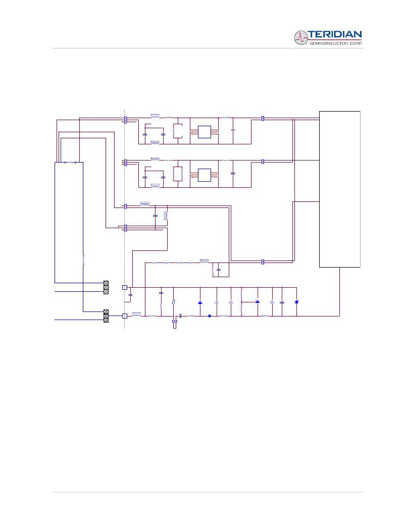
�A� top-level� schematic� of� the� board� connected� to� a� shunt� resistor� is� shown� in� Figure� 1-10.�
�L6�
�IA�
�J3�
�IA_IN�
�R110�
�R14�
�IA�
�TP21�
�IA�
�6511�
�HDR3�
�GND�
�GND�
�FERRITE�
�0�
�U1�
�750�
�HDR2�
�V3P3�
�C17�
�1000pF�
�L7�
�C18�
�1000pF�
�R24�
�10K�
�1�
�2�
�3�
�A1� AC1�
�C1� C2�
�AC2� A2�
�BAV99DW�
�6�
�5�
�4�
�C8�
�1000pF�
�V3P3�
�FERRITE�
�L4�
�IB�
�SHUNT1�
�J16�
�IB_IN�
�R111�
�R104�
�IB�
�TP22�
�IB�
�HDR3�
�GND�
�GND�
�FERRITE�
�0�
�U6�
�750�
�HDR2�
�C11�
�1000pF�
�C10�
�1000pF�
�R106�
�3.4�
�R107�
�3.4�
�1�
�2�
�3�
�A1�
�C1�
�AC2�
�AC1�
�C2�
�A2�
�6�
�5�
�4�
�C29�
�1000pF�
�L5�
�BAV99DW�
�V3P3�
�FERRITE�
�JP17�
�L3�
�FERRITE�
�VA�
�V3P3�
�V3P3J2�
�HDR2�
�JP16�
�HDR3�
�C15�
�1nF�
�GND�
�V3P3_JUMPER�
�L1�
�FERRITE�
�L2�
�TP4�
�LOAD�
�R18�
�R17�
�R16�
�R15�
�V3P3�
�V3P3�
�2M�
�274K�
�270K�
�700�
�FERRITE�
�R32�
�750�
�C9�
�1000pF�
�VA�
�HDR2�
�GND�
�V3P3J2�
�NEUTRAL�
�J9�
�1�
�NEUTRAL�
�V3P3_JUMPER�
�C32�
�C14�
�1nF�
�30nF�
�2200uF,� 16V�
�8.06K�
�TL431�
�GND�
�R8�
�RV1�
�510V�
�D3�
�1N4736A�
�+� C1�
�+� C2�
�10uF�
�8�
�+� C4�
�33uF�
�C5�
�0.1uF�
�D10�
�UCLAMP3301D�
�LIVE�
�J4�
�1�
�LIVE�
�L8�
�FERRITE�
�R118�
�10,� 2W�
�1�
�0.47uF,� 1000Vdc�
�C6�
�R6�
�100,� 2W�
�6.8V,� 1W�
�D4�
�1N4148�
�R7�
�130�
�25.5K�
�R20�
�0�
�GND�
�JP2�
�HDR2�
�Figure� 1-10:� Current� Shunt� Top-Level� Schematics� (Shown� for� the� 2-Layer� Board)�
�1.8.7� ADJUSTING� THE� DEMO� BOARD� TO� DIFFERENT� VOLTAGE� DIVIDERS�
�The� 6511� Demo� Board� comes� equipped� with� its� own� network� of� resistor� dividers� for� voltage� measurement�
�mounted� on� the� PCB.� The� resistor� values� (for� the� 4-layer� Demo� Board)� are� 2.5477M� ?� (R15-R21,� R26-R31�
�combined)� and� 750� ?� (R32),� resulting� in� a� ratio� of� 1:3,393.933.� This� means� that� VMAX� equals�
�176.78mV*3,393.933� =� 600V.� A� large� value� for� VMAX� has� been� selected� in� order� to� have� headroom� for�
�overvoltages.� This� choice� need� not� be� of� concern,� since� the� ADC� in� the� 71M6511� has� enough� resolution,�
�even� when� operating� at� 120Vrms� or� 240Vrms.�
�If� a� different� set� of� voltage� dividers� or� an� external� voltage� transformer� is� to� be� used,� scaling� techniques�
�similar� to� those� applied� for� the� current� transformer� should� be� used.�
�In� the� following� example� we� assume� that� the� line� voltage� is� not� applied� to� the� resistor� divider� for� VA� formed�
�by� R15-R21,� R26-R31,� and� R32,� but� to� a� voltage� transformer� with� a� ratio� N� of� 20:1,� followed� by� a� simple�
�resistor� divider.� We� also� assume� that� we� want� to� maintain� the� value� for� VMAX� at� 600V� to� provide� headroom�
�for� large� voltage� excursions.�
�Revision� 5.4�
�?� 2005-2007� TERIDIAN� Semiconductor� Corporation�
�Page:� 29� of� 115�
�发布紧急采购,3分钟左右您将得到回复。
相关PDF资料
71M6513H-DB
BOARD DEMO 71M6513H ENERGY METER
71M6515H-DB
BOARD DEMO 71M6515H ENERGY METER
71M6521FE-DB
BOARD DEMO FOR 71M6521FE
71M6531F-DB
BOARD DEMO 71M6531F
71M6533-DB
BOARD DEMO 71M6533
71M6534H-DB
BOARD DEMO 71M6534H
71M6541F-DB
DEMO BOARD 71M6541F
71M6543F-DB-CT
DEMO BOARD 71M6543F-DB-CT
相关代理商/技术参数
71M6511H
制造商:TERIDIAN 制造商全称:TERIDIAN 功能描述:Single-Phase Energy Meter IC
71M6511H-DB
功能描述:开发板和工具包 - 8051 71M6511H Demo Brd RoHS:否 制造商:Silicon Labs 产品:Development Kits 工具用于评估:C8051F960, Si7005 核心: 接口类型:USB 工作电源电压:
71M6511H-IGT
制造商:TERIDIAN 制造商全称:TERIDIAN 功能描述:Single-Phase Energy Meter IC
71M6511H-IGT/F
功能描述:计量片上系统 - SoC Highly Integrated SoC w/MCU Core RoHS:否 制造商:Maxim Integrated 核心:80515 MPU 处理器系列:71M6511 类型:Metering SoC 最大时钟频率:70 Hz 程序存储器大小:64 KB 数据 RAM 大小:7 KB 接口类型:UART 可编程输入/输出端数量:12 片上 ADC: 安装风格:SMD/SMT 封装 / 箱体:LQFP-64 封装:Reel
71M6511H-IGTR
制造商:Maxim Integrated Products 功能描述:RESID. HI PRECISION METR (1P, .1%) - Tape and Reel
71M6511H-IGTR/F
功能描述:计量片上系统 - SoC Highly Integrated SoC w/MCU Core RoHS:否 制造商:Maxim Integrated 核心:80515 MPU 处理器系列:71M6511 类型:Metering SoC 最大时钟频率:70 Hz 程序存储器大小:64 KB 数据 RAM 大小:7 KB 接口类型:UART 可编程输入/输出端数量:12 片上 ADC: 安装风格:SMD/SMT 封装 / 箱体:LQFP-64 封装:Reel
71M6511-IGT
制造商:TERIDIAN 制造商全称:TERIDIAN 功能描述:Single-Phase Energy Meter IC
71M6511-IGT/F
功能描述:计量片上系统 - SoC Highly Integrated SoC w/MCU Core RoHS:否 制造商:Maxim Integrated 核心:80515 MPU 处理器系列:71M6511 类型:Metering SoC 最大时钟频率:70 Hz 程序存储器大小:64 KB 数据 RAM 大小:7 KB 接口类型:UART 可编程输入/输出端数量:12 片上 ADC: 安装风格:SMD/SMT 封装 / 箱体:LQFP-64 封装:Reel